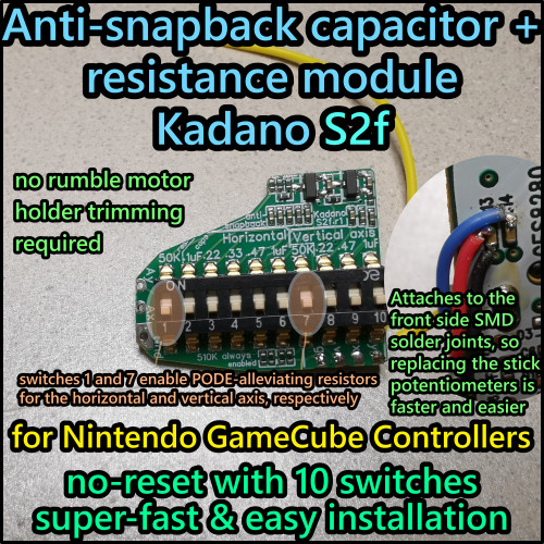
This capacitance module makes your controller no longer have snapback. With 10 switches to set capacitance, 6 for the horizontal axis and 4 for vertical, you have a lot of fine control.
This newer design (product code S2e) has a fully modular snapback module (that can easily be replaced by the end user without soldering) and an add-on slot for future extra function boards, such as the resistance circuits that are supposed to increase effective potentiometer lifespan, which were recently documented by Rienne and are currently in the testing / experimental stage (available under a separate listing).
Due to the layout designed for front wiring, cutting or replacing the black rumble holder is not needed here. That also makes replacing stick potentiometers in the future less of a hassle, as there are no wires in the way that you need to move out of the way first.
In this aspect, the S2e modules are superior to both "old-school" capacitor modules with 4 wires going to the potentiometer solder pads and to newer flexible PCB designs. Compared to the latter, the S2e design can be expected to last longer, as there is no strain to any solder pads when replacing stick potentiometers (whereas flex PCB pads can get burned quite easily) and also no strain to the PCB or solder connections from rumble, transportation or dropping the controller (all strain gets absorbed by the flexible silicone cables).
So in short, if you want something durable, reliable and future-proof, the S2e capacitor module style is your top choice.
These modules are very compact and fit into the handles easily. For installing, you need a screwdriver to open the controller (sold separately), a soldering station and superglue for fixing the wires in place.
Additional flux is recommended, but not strictly needed as the wires are pre-tinned with extra flux by me.
Installation time: ~10 minutes. Snapback adjustment time (when using SmashScope / oscilloscope): ~3 minutes.
Installation steps:
1. Open the controller, take out the mainboard.
2. Remove the yellow sticky foam tape protective layer and stick the main module (that has the 4 wires attached) to the backshell as shown in the photos.
3. Solder the wires to the front side SMD capacitor pins as shown on the photo. Fine tweezers are recommended for this step.
4. Move the wires into the positioning shown on the photos and fix them to the board with very small amounts of superglue.
5. Insert the controller mainboard into the front shell again.
6. Adjust capacitance: flipping switches up enables them, 1-6 are for the horizontal axis and 7-10 are for the vertical axis.
The more capacitance you activate (by flipping the switch up), the more you reduce snapback. For example, flipping up swtiches 3, 5 and 9 gives you .22+.47 = .69 uF for the horizontal axis and .47 uF for the vertical axis, which is the ideal amount most of the time (on new / lightly used controllers with default stick knobs).
B-stock: around 5-10% of the dip switches that I used have some of the 10 switches not always turn on properly when in up (on) position. I mark the affected numbers with red color; those will only turn on if the switch is pushed towards the on position very strongly, sometimes even pushing it down (towards the PCB, not towards the off position) is required for the switch to connect the two contacts. Ideally, you avoid turning on the affected positions completely. Usually the remaining switches are enough to get the capacitance you need added together.
B-stock modules have 1-4 switches marked in red color and are sold at a 33% discount.
Regular stock modules are tested for continuity by me and have been confirmed to have all 10 switches fully functional regardless of how strongly they are flipped to on position.
PCB type: lead-free, compliant with RoHS (Restriction of Hazardous Substances, such as lead).
Solder type: lead-free (RoHS compliant).
Wire type: silicone coated, more flexible and won't melt / cause toxic fumes during soldering, as 'normal' PVC wires do. 28 AWG size.
Designed for usage in Nintendo Gamecube controllers.
PCB design and original idea by me (Kadano), PCBs produced and partially assembled by factory. Soldering of the 10x switch and the 4 wires (pre-tinned for easy soldering) as well as quality control done by me.
Additional instructions and details: https://sites.google.com/view/kadano-s2d
ENIG (green boards) are gold-plated which theoretically gives them an increased lifespan over HASL. It's unlikely to really make a difference unless you let your controller get wet on the inside, in which case you likely have bigger problems with other mainboard components though, so feel free to decide based on which color you like more.


