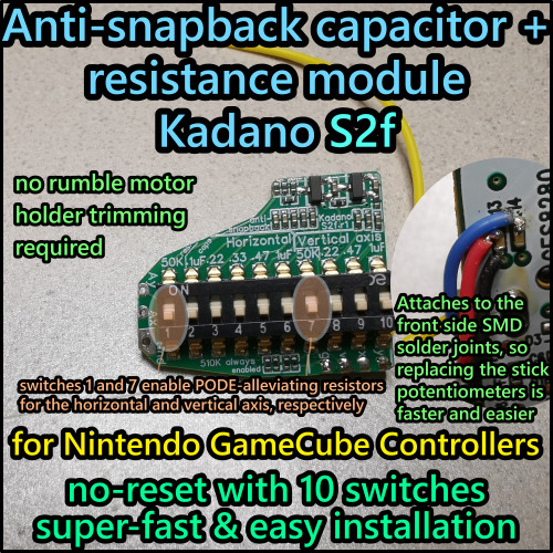
These tiny daughter modules are supposed to prolong the effective lifespan of Gamecube controller potentiometers by providing a resistance path from signal to 3.3V and ground, hopefully leading inputs to be stabilized to neutral more quickly. The idea for these resistance paths originally came from Rienne and has been referred to as "heartbeat mod".
Their main intended usage is to be coupled with my S2e modules, which have an add-on socket that these fit into. They are snapped in, no soldering required. The only tool you need is a tripoint screwdriver to open the controller. However, keep in mind that without an existing S2e module or Trigger base module from me installed in your controller, these are useless to you.
The idea here is to keep the signal output of heavily used potentiometers usable for longer, limiting input drift.
You can see the effect of this, measured in SmashScope on a 480i Wii, in the second photo of this listing. Of the 6 sub-images, the top right one shows a light PODE stick potentiometer with 0.47 uF enabled. This is usually too much for desirable inputs, here it was just enabled to simulate a high PODE signal curve to see what effect different resistance paths have.
The lower the resistance, the stronger the effect – 510K only has a mild effect, whereas 5-33K have a very strong effect.
In my testing, only resistance values of 50K and lower have had substantial effects on signal response in reducing drifting. Rienne has reported seeing improvements at ~500K already, but visual measurements have not been provided yet.
It's possible that the added capacitance plays a role, so with controllers that have drifting, but also still have snapback if used with 0 uF capacitance, it's likely that lower resistance paths (say 20K-50K) are more likely to be ideal than on controllers that have drifting but no snapback even with 0 uF capacitance.
By tendency, the more worn your potentiometers are, the lower you'll want to go in terms of resistance. The lowest two sets, especially 5K+10K, are highly experimental and it's not impossible for stick response to be worse for certain inputs.
Unlike with modules where the different resistances are toggled through switches, which necessitates a constant added path from signal to ground, even when the switches are turned off, these snap-in modules only have this added path if there's a module inserted. In theory, this slightly reduces electricity strain of the controller and console, however from my understanding the effect of this should be negligible. It was one of the reasons why I went for this modular design, but I don't think it's of much importance.
In total, this is still a fairly experimental mod, however for relatively little money, these modules can bring a chance of extending your controller potentiometers' usable lifespan by ~4-12 months, rather than having to send the controller to a modder to have the potentiometers replaced for new ones.
That is, assuming that you either install one of my S2e snapback modules first, or had someone install one before.
These resistance modules are also compatible with my Trigger base modules. There's a good chance that the resistance path can reduce / eliminate trigger drifting ("lightshield bug") as well, although I have not gotten the chance to test this yet.
PCB type: lead-free, ENIG, compliant with RoHS (Restriction of Hazardous Substances, such as lead).
Solder type: lead-free (RoHS compliant).
Designed for usage in Nintendo Gamecube controllers.
Original resistance path idea by rienne. PCB design and idea of using modular sockets by me (Kadano), PCBs produced and partially assembled by factory. Cut and trimmed by me.
Additional details (testing results): https://photos.app.goo.gl/PowmenJzRb6Dx4mZ7


