

")

 very close to both the wire's stripped end and the SMD solder pad for 3 seconds to form a good solder joint")

 very close to both the wire's stripped end and the SMD solder pad for 3 seconds to form a good solder joint")

 very close to both the wire's stripped end and the SMD solder pad for 3 seconds to form a good solder joint")

 very close to both the wire's stripped end and the SMD solder pad for 3 seconds to form a good solder joint")


This capacitance & heartbeat module makes your controller no longer have snapback. With 8 switches to set capacitance, 5 for the horizontal axis and 3 for vertical, you have a lot of fine control. In addition, this module has a permanent resistance path from each signal to 3.3V and ground respectively, through 510 kOhm of resistance, and a toggle for each resistance to be lowered to ~46 kOhm of resistance, known as "heartbeat" functionality.
The default 510 kOhm is enough to alleviate the negative effects of undesirable light to moderate PODE, while the lower resistance (and thus stronger electricity flow) you have with the toggle switches 1 (for the horizontal axis) / 7 (for the vertical axis) should alleviate even rather high PODE, which otherwise causes input drifting (such as getting side-B instead of aerial turnaround neutral-B, or forward aerials instead of neutral aerials after dashing forward).
Due to the layout designed for front wiring, cutting or replacing the black rumble holder is not needed here. That also makes replacing stick potentiometers in the future less of a hassle, as there are no wires in the way that you need to move out of the way first.
In this aspect, this S2f module design is superior to both "old-school" capacitor modules with 4 wires going to the potentiometer solder pads and to newer flexible PCB designs. Compared to the latter, the S2f design can be expected to last longer, as there is no strain to any solder pads when replacing stick potentiometers (whereas flex PCB pads can get burned quite easily) and also no strain to the PCB or solder connections from rumble, transportation or dropping the controller (all strain gets absorbed by the flexible silicone cables).
So in short, if you want something durable, reliable and versatile, the S2f capacitor module style is your top choice.
These modules are very compact and fit into the handles easily. For installing, you need a screwdriver to open the controller (sold separately), a soldering station and superglue for fixing the wires in place.
Additional flux is recommended, but not strictly needed as the wires are pre-tinned with extra flux by me.
Installation time: ~10 minutes. Snapback adjustment time (when using SmashScope / oscilloscope): ~3 minutes.
Installation steps:
1. Open the controller, take out the mainboard.
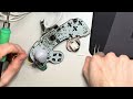
2. Remove the yellow sticky foam tape protective layer and stick the main module (that has the 4 wires attached) to the backshell as shown in the photos. This is easiest with dolphin-shape tweezers.
3. Solder the wires to the front side SMD capacitor pins as shown on the photos. Fine tweezers are recommended for this step. Make sure to have a good amount of solder on your tip so that it flows to the SMD solder pad and to the wire well.
4. Optional: fix the yellow wire in place with tape or with super glue.
5. Insert the controller mainboard into the front shell again.
6. Adjust capacitance: flipping switches up enables them, 2-6 are for the horizontal axis and 8-10 are for the vertical axis.
7. If you recognize stick inputs staying active longer than you input them, enable the respective resistance toggle (switch 1 for the horizontal axis / switch 7 for the vertical axis).
The more capacitance you activate (by flipping the switch up), the more you reduce snapback. For example, flipping up swtiches 3, 5 and 9 gives you .22+.47 = .69 uF for the horizontal axis and .47 uF for the vertical axis, which is the ideal amount most of the time (on new / lightly used controllers with default stick knobs).
PCB type: lead-free, compliant with RoHS (Restriction of Hazardous Substances, such as lead).
Solder type: lead-free (RoHS compliant).
Wire type: silicone coated, more flexible and won't melt / cause toxic fumes during soldering, as 'normal' PVC wires do. 28 AWG size.
If you opt for the bulk option, where only the components but not the wires are pre-soldered, I recommend also using silicone wire (not included, but available on AliExpress and Amazon). Best practice is to use flux gel applied to the solder pads before soldering the wires and fully cleaning it after soldering the wires with Q-tips soaked in ethanol or isopropylic alcohol followed by toilet paper or similar soaked in alcohol. (Flux residue can easily be spread to digital button contact pads, where it will cause input unreliability, so it's best to prevent that at the earliest possible point.)
Designed for usage in Nintendo Gamecube controllers.
Heartbeat concept originally invented by Rienne. PCB design and front-wiring idea by me (Kadano), PCBs produced and partially assembled by factory. Soldering of the 4 wires (pre-tinned for easy soldering) as well as quality control done by me.
Additional instructions and details: https://sites.google.com/view/kadano-s2d
1 Review Hide Reviews Show Reviews
-
S2f & S2d modules
Extremely high quality modules, open communication, and exceptional reference images and guides make for a seamless installation. Truly the industry standard.


 daughter module (only for S2e snapback modules and Tb trigger modules)")
